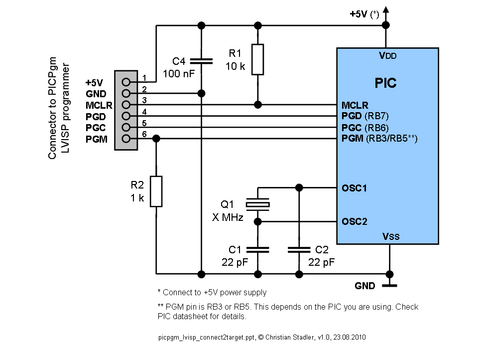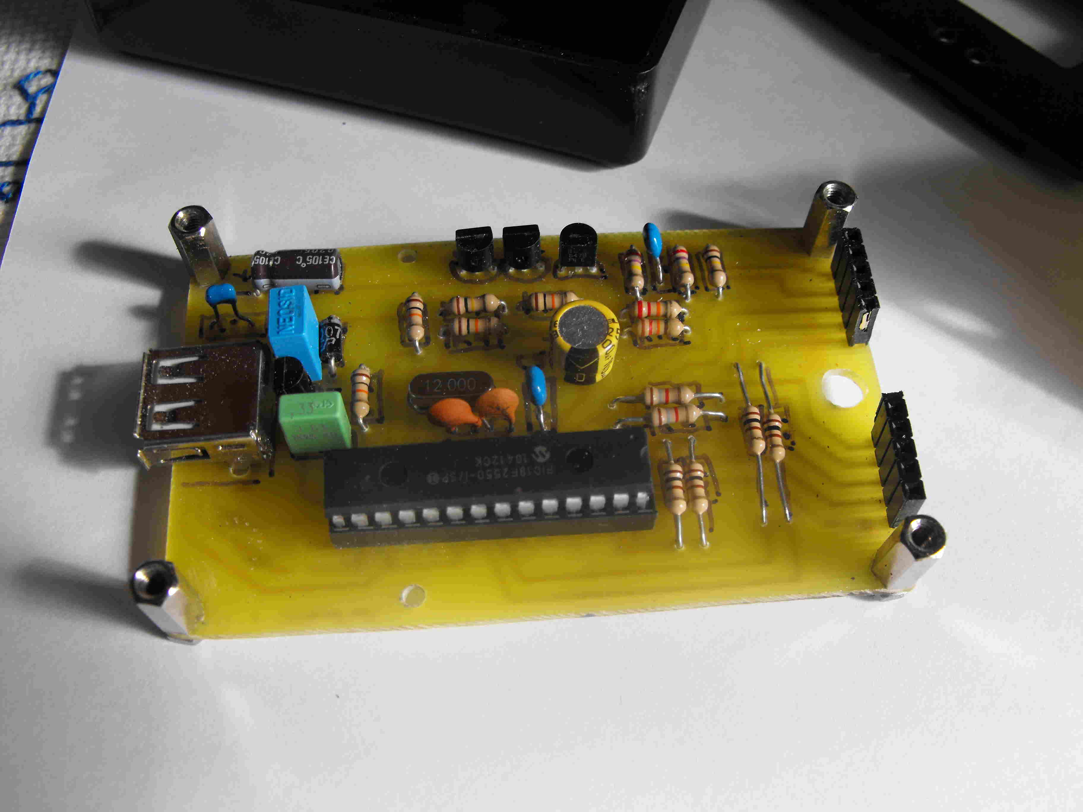

LM78L05 are standard components and are easy to find. On a bench supply and frying your microchip. It's just too easy to accidentally apply the wrong voltage by turning the dial LM317 saves you needing an accurate bench power supply - you can use a dc powerīlock - anything that supplies more than about 15V dc. Tried to use it I got all kinds of random results so it is worth adding Transmission line termination lets you use the pic programmer circuit at theĮnd of a long cable - I am using a normal parallel cable ~6 feet long. Supply steering diode (stops you reverse connecting theħ4LS244 to 74HCT244 because I had one handy!ġ0k resistors instead of 2k - just easier if they are all the Voltage regulator to get 11.6 volts and protect the circuit Transmission line termination - lets it work over a long.Has a few modifications that are useful and easy to do: Responsible for any damage to your computer.

For initial testing it is best if you use a spare (old computer).īuilding this project is your own responsibility and I can not be held This includes checking for shorts between each pin at the parallel port on yourĬircuit.
Usb pic programmer schematic how to#


 0 kommentar(er)
